

- 2024/04/26 初心者向け粒子法熱流体解析入門コースのご案内
- 2024/04/16 「SPH粒子法による熱流体解析ソフトPHACT_Flow」サイトを開設(こちらから)
- 2024/01/15 「たま未来・産業フェア」(2024年1.26-1.27)出展内容のご案内_________________________________________________________________________________________
- 2023/12/27 年末年始休業のお知らせ
- 2023/12/11 「たま未来・産業フェア」(2024年1.26-1.27)出展のお知らせ
- 2023/10/10 「中小企業 新ものづくり・新サービス展」の出展内容のご案内
- 2023/09/04 「中小企業 新ものづくり・新サービス展」(2023.12.6~12.8)出展決定
- 2023/08/07 夏季休業のお知らせ
- 2023/07/21 動画によるTrueGrid 新バージョンV.4.0.2の事例紹介を追加
- 2023/06/30 && 最近の話題 コーナー &&を追加更新(動画)
- 2023/04/15 TrueGrid 新バージョンV.4.0.2の主な機能を用いた適用事例の紹介
- 2023/03/31 解析事例を追加更新
- 2023/02/07 && 最近の話題 コーナー&& を追加更新
_________________________________________________________________________________________ - 2022/12/27 年末年始の休業のお知らせ
- 2022/12/15 MpaveMeshの操作手引書Rev.1の新規リリースのお知らせ
- 2022/11/30 プリプロセッサMpaveMeshのマニュアル(日本語版)Rev.3のリリースのお知らせ
- 2022/09/04 解析事例の内容を分かり易く理解・検索できるようサムネイル画像を追加
- 2022/07/25 「産業交流展2022」(期間:2022年10月19日~ 21日)出展のお知らせ
- 2022/06/30 && 最近の話題 && コーナーを逐次追加更新
- 2022/04/07 粒子法による鋳造解析ソフトPHACT_CASTの機能および解析事例追加
- 2022/03/11 SPH粒子法による熱流体解析ソフトPHACT_Flow V.2.1リリース開始のお知らせ
_________________________________________________________________________________________
- 2021/12/28 年末年始の休業のお知らせ
- 2021/11/02 「令和3年度 新技術創出交流会 Web製品展示会出展(11月1日~2022年3月31日)のご案内
- 2021/09/24 「中小企業 新ものづくり・新サービス展」Web出展(9月下旬~2022年2月25日)のご案内
- 2021/09/10 セミナー「高精度の解析を実現する優れた六面体メッシュ生成手法の提案Ⅱ」ご案内
- 2021/08/13 Hexaメッシュ生成ソフトTrueGridの新バージョンV.4.0.2のリリース開始のお知らせ
- 2021/08/09 国際学会 WCCM-APCOM YOKOHAMA 2022 参加・講演のお知らせ
- 2021/05/28 連成解析プログラムMPACT/Mpave解析事例集の更新のお知らせ
- 2021/04/30 連成解析プログラムMPACT/MpaveのTechnical Noteを拡充しました
- 2021/01/15 「ヴァーチャル産業交流展2020」(期間:1月20日~2月19日)出展内容のご案内
- 2021/01/08 1月20日~2月19日開催の「ヴァーチャル産業交流展2020」出展決定のお知らせ
- 2021/01/08 「オンライン彩の国ビジネスアリーナ」(開催期間:1月8日~2月8日) 出展中のお知らせ
____________________________________________________________________________________________
- 2020/12/26 年末年始休業のお知らせ
- 2020/12/18 2021年1月8日~2月8日開催の「オンライン彩の国ビジネスアリーナ」出展のお知らせ
- 2020/11/02 新しくWebサイトメニューに動画を含む「解析事例」を開設しました
- 2020/10/23 Webセミナー「ガス巻込み欠陥を予測する鋳造シミュレーション技術」のご案内
- 2020/10/21 12月7日~9日開催の「中小企業 新ものづくり・新サービス展」出展内容掲載
- 2020/10/01 12月7日~9日開催の「中小企業 新ものづくり・新サービス展」出展決定のお知らせ
- 2020/09/02 オンライン(Web)セミナーを開始
- 2020/08/25 事務所移転のお知らせ(新しい事務所情報)
- 2020/06/26 && 最近の話題 && コーナーを逐次更新
- 2020/03/06 動画による解析事例を紹介するサイトを開設(こちらから)
- 2020/01/17 2月26日開催の初心者向け粒子法固体解析入門コースのご案内
- 2020/01/17 2月25日開催の初心者向け粒子法流体解析入門コースのご案内
____________________________________________________________________________________________
- 2019/12/26 年末年始休業のお知らせ
- 2019/11/20 12月2日開催の「粒子法解析のためのプリポストTenGun紹介セミナー」のご案内
- 2019/11/15 11月19日開催の「初心者向けGPGPU計算技術に関するコース」のお知らせ
- 2019/10/04 10月25日開催の「初心者向け粒子法入門」コースのご案内
- 2019/09/25 11月13日~15日開催の「産業交流展2019」出展のご案内
- 2019/08/16 10月29日開催の粒子法の最新技術動向セミナーのご案内
- 2019/08/16 9月18日~19日開催の「新技術創出交流会」出展のご案内
- 2019/07/10 7月29日開催のCAEセミナーのご案内
- 2019/06/07 7月29日開催のCAEセミナーのお知らせ
- 2019/03/15 TrueGrid説明内容を大幅に更新
____________________________________________________________________________________________
- 2018/12/18 年末年始休業のお知らせ
- 2018/12/18 弊社は2019年度3月開催の国際学会ICCES2019に参加・協力、論文発表します
- 2018/10/09 12月11~13日開催「中小企業 新ものづくり・新サービス展」のご案内
- 2018/09/24 ICTP-IAEA Activities on Innovative NESにおいてLecture
- 2018/09/21 10月5日開催の「技術連携交流会」出展のご案内
- 2018/08/07 「中小企業 新ものづくり・新サービス展」(12月11日~13日開催)出展決定
- 2018/07/19 9月19、20日開催の「新技術創出交流会」出展のご案内
- 2018/06/14 国際学会WCCMⅩⅢ(7月22日~27日開催)において論文発表
- 2018/06/01 日本計算工学会論文集(共著者として)に掲載されました。
- 2018/05/11 第23回計算工学講演会において論文発表
- 2018/04/13 Webサイトを更新
- 2018/03/02 実務を重視したACT解析技術習得コース(前半期)のご案内
- 2018/02/26 3月16日に非線形解析プログラム研究会で講演
- 2018/01/15 新しい弊社Webサイト公開
- 2017/12/26 年末年始休業のお知らせ
- 2017/12/26 新しいWebサイト公開のお知らせ
- 2017/10/16 ACT特別CAEセミナー名古屋会場追加のご案内
- 2017/09/29 平成29年度「地域イノベ・技術連携交流会」への参加・出展
- 2017/09/22 日本鋳造工学会第170回全国講演大会において論文発表
- 2017/09/22 ACT特別CAEセミナーのご案内
- 2017/08/10 夏季休業のお知らせ:8月11日(金)~15日(火)
- 2017/05/19 「粉体成形加工プロセスのシミュレーションセミナーin Nagoya
- 2017/03/17 国際学会ICCES2017に参加、論文発表
- 2017/03/03 第22回計算工学講演会において論文発表
- 2017/01/06 「粉体成形加工プロセスのシミュレーション技術」セミナーのご案内
- 2017/01/06 研究開発室移転のお知らせ
- 2016/12/27 年末年始休業のお知らせ
- 2016/10/21 国際粉体工業展東京2016出展イベントに協力参加
- 2016/10/21 新しいTrueGrid V3.1.3のチュートリアル・マニュアルを更新
- 2016/10/20 新バージョンSpinFire Ultimate V11.3.2リリース開始
- 2016/6/30 新バージョンSpinFire Ultimate V11.3リリース開始
- 2016/3/18 粉体の計測技術、圧縮成形解析に関する特別セミナーのご案内
- 2016/1/08 SPH解析紹介セミナー「SPH(粒子)法とは」のご案内
- 2015/12/25 年末年始休業のお知らせ
- 2015/9/24 「東京都新技術・新工法展示商談会」出展のご案内
- 2015/7/16 TrueGrid チュートリアル・ビデオマニュアルを更に大幅に更新
- 2015/4/26 ICEPより「Outstanding Technical Paper Award」受賞のご報告
- 2015/4/26 「固体解析SPHinx-SOLID体験セミナーのご案内」のご案内
- 2015/2/17 新バージョンTrueGrid V.3.1リリース開始
- 2014/12/26 年末年始休業のお知らせ
(2014年12月27日(土)~2015年1月4日(日);5日(月)より業務開始) - 2014/12/03 「SPH粒子法アドバンストテクノロジーセミナー」のご案内
- 2014/11/04 「国際粉体工業展東京2014」出展(協賛)のご案内
- 2014/9/11 理研セミナー「SPH粒子法を知る」のご案内」
- 2014/8/05 体験セミナー「解析事例から学ぶSPH法解析の魅力」ご案内
- 2014/5/16 「SPH法による固体解析特別セミナーin Nagoya」ご案内
- 2014/4/17 「SPH法による粉体解析特別セミナー」のご案内
- 2014/3/11 「SPHinx「テーマ別紹介・体験コース(3月~5月分)」ご案内
- 2014/3/7 「TrueGrid チュートリアル・ビデオマニュアル」を大幅に更新。
- 2013/12/27 年末年始休業のお知らせ
(2013年12月28日(土)~2014年1月3日(金);6日(月)より業務開始) - 2013/12/27 2014年度「SPH解析特別セミナーin Nagoya」のご案内
- 2013/12/26 2014年度SPHinx「テーマ別紹介・体験コース」ご案内
- 2013/11/13 SPH解析特別セミナー「SPH解析が目指す世界」ご案内
- 2013/10/1 新バージョンSPHinx-FLOW2D Ver.1.2リリース開始
- 2013/9/30 「SPHinx「テーマ別紹介・体験コース(10月、11月分)」ご案内
- 2013/9/17 新バージョンSPHinx-SOLID2D Ver.1.2リリース開始
- 2013/8/19 新バージョンSpinFire10.6リリース開始
- 2013/7/22 「SPHinx「テーマ別紹介・体験コース(8月、9月分)」ご案内
- 2013/6/13 「容易に使いこなせるSPHinxソフトの入門講座(第二回)」ご案内
- 2013/6/8 SPHinxソフト 「テーマ別紹介・体験コース(無料)」スタート
- 2013/6/7 「テクノトランスファーinかわさき2013」への出展のご案内
- 2013/4/11 「容易に使いこなせるSPHinxソフトの入門講座」ご案内開始。
- 2013/3/27 新SpinFire10.5に対応したチュートリアルマニュアル作成
- 2013/1/23 「テクニカルショウ ヨコハマ 2013」参加のご案内
- 2013/1/21 新バージョンSpinFire10.5リリース開始
- 2013/1/18 「SPH粒子法の基礎と応用講座(第四回)」案内開始。
- 2012/12/28 年末年始休業のお知らせ
(2012年12月29日(土)~2013年1月3日(木)) - 2012/12/28 「SPH粒子法の基礎と応用講座(第四回)」開催のお知らせ。
- 2012/11/13 デジタルデザインコミュニケーションSpinFireのサイトを刷新。
無償の情報閲覧専用ビューワーSpinFire Reader提供開始。 - 2012/11/5 新バージョンSpinFire10.4リリース開始
- 2012/10/2 「SPH粒子法の基礎と応用講座(第三回)」事例紹介。
- 2012/10/2 SPH粒子法の「各種分野の適用事例」のコーナーを更新しました。
- 2012/9/30 超音波によるモニタリングPWASの「各種分野での使用例」を更新。
- 2012/8/11 「SPH粒子法の基礎と応用講座(第三回)」のご案内開始。
- 2012/8/10 夏季休業のお知らせ:8月13日(月)~15日(水)
- 2012/6/25 WCCM2012に参加、発表
- 2012/5/14 「SPH粒子法の基礎と応用講座(第二回)」のご案内開始。
- 2012/4/23 第17回計算工学講演会において発表、およびカタログ展示
- 2012/2/28 SPH粒子法の「各種分野の適用事例」のコーナーを新設しました。
- 2012/1/31 「現場設計・解析技術者のためのSPH粒子法の基礎と応用講座」
- 2012/1/6 高品質メッシュ作成プロダクトTrueGrid特別セミナーのご案内。
- 2011/12/23 ビジネスアリーナ2012出展
- 2011/12/6 新バージョンSpinFire10.1リリース開始
- 2011/11/24 12月18日開催「医療機器デバイス連携交流会」展示参加
- 2010/11/8 TrueGridチュートリアルコーナーを新設しました。
新しくTrueGridチュートリアル ビデオ・マニュアルを作成 - 2011/10/20 産業交流展2011に出展(更新)
- 2011/9/27 超音波による構造物の新しい健全性モニタリングシステム
を更新しました。 - 2011/9/20 新バージョンSpinFire10.0リリース開始
- 2011/9/08 「地域イノベ・技術連携交流会」に参加、出展
開催期間:10月7日(金)12:30 ~ 18:30
会場:東京都中野区中野サンプラザ - 2011/8/26 2011年度後半期(9月~) 新体験セミナーのご案内
- 2011/8/05 産業交流展2011に出展
開催期間:10月26日(水)~28日(金)
会場:東京ビッグサイト 東5・6ホール - 2011/8/01 日本応用数理学会2011年度年会予稿集に弊社広告掲載
会期:9月14日(水)~16日(金)
会場:同志社大学今出川キャンパス - 2011/5/23 第16回計算工学講演会会場においてカタログ展示
- 2011/5/17 「人とくるまのテクノロジー展2011」においてカタログ展示
- 2011/4/30 超音波によるモニタリングPWAS、及び適用例を更新しました。
- 2011/4/5 工業用内視鏡の各種分野での使用例を更新しました。
長い配管の管内部の検査に有効な「管検査カメラシステム」追加 - 2011/3/19 TrueGridのDemonstrationビデオコーナーを新設しました。
- 2011/3/1 2011年度前半期(~6月) 新体験セミナーのご案内。
- 2011/2/7 医療用解析ソフトSPH Medical Solutionを更新しました。
- 2011/1/26 「Prometech Techno Forum in 名古屋」にて講演。
講演題目:SPH粒子法によるバイオメカニックス分野への応用 - 2011/1/20 米国South Carolina大学LAMSSと超音波による新しい安全性
モニタリングシステムに関し、技術・販売協力体制を強化
(製品紹介) - 2011/1/7 開催予定のセミナー・イベントを掲載しました。
- 2011/1/5 ホームページをリニューアルしました。
- 2010/12/27 年末年始休業のお知らせ
(2010年12月29日(水)~2011年1月3日(月)) - 2010/12/7 12月17日(金)開催の第35回ミニTAMA東部会に参加
- 2010/12/6 12月3日開催のACT特別セミナーの報告を掲載
- 2010/11/1 12月3日(金)開催の特別セミナー:
[超音波による構造物の新しい安全性モニタリング
システム]のご案内。 - 2010/10/28 [報告] TAMAビジネスプランコンテストにおいて
栄えある賞を受賞 - 2010/10/21 四辺形シェル構造自動メッシャー[AutoQuad]、
今年末にリリースを計画 - 2010/9/24 新バージョンSpinFire9.0を9月からリリース開始
- 2010/9/21 10月27日(水)開催のビジネスコンテスト2010で発表
- 2010/9/20 10月15日(金)開催の第10回あおしんビジネス
マッチング大会に出展 - 2010/9/10 工業用内視鏡サイトに各種分野での使用例を追加。
- 2010/8/26 9月17日(金)開催のスペシャルトピックセミナー
[塑性加工解析Seminar2010]の内容更新。 - 2010/8/11 連成解析ソルバーMPACT、及び次世代Front-end Mpaveの
製品スライドショーを更新しました。 - 2010/8/10 日英翻訳支援ソフトJEMAPの製品スライドショーを追加。
- 2010/7/21 「実験・計測システム」内に工業用内視鏡による適用サイト
を公開しました。 - 2010/7/13 9月17日(金)開催のスペシャルトピックセミナー
[塑性加工解析Seminar2010]のご案内。 - 2010/6/28 2010年度後半期(7月~) 体験セミナーのご案内。
- 2010/6/17 Front Pageに「最近のトピックスと新製品(Latest News
and Products)」のコーナーを新設しました。 - 2010/5/24 Dr. Pedro MarcalのBlogを更新しました。
- 2010/5/6 ACT_CAEメルマガ配信を開始しました。
- 2010/4/30 カールストルツ・エンドスコピー・ジャパン株式会社様と
代理店契約を締結。 - 2010/4/28 MPACTカスタマイズ・サイトを公開しました。
- 2010/3/20 SpinFire Tutorial Siteを公開しました。
- 2010/3/5 3月12日(金)開催の「第89回ミニTAMA西部会
(交流会)」において講演。 - 2010/2/20 2010年度前半期 体験セミナーのご案内。
- 2010/2/3 TrueGrid Galleryを公開しました。
- 2010/1/21 ダウンロードサイトを正式に公開しました。
- 2010/1/8 Dr. Pedro MarcalのBlogを公開しました。
- 2009/12/1 ホームページをリニューアルしました。
- 2009/10/26 TrueGrid 操作例題の掲載を開始しました。
- 2009/10/25 体験セミナー開始のお知らせ
SpinFire Pro8.4体験セミナー,
TrueGrid体験セミナー - 2009/10/18 新プロダクト資料を掲載しました。
ANLAP/概要説明等, JEMAP/GettingStated等 - 2009/10/17 各種プロダクト資料を掲載しました。
MPACT, Mpave/概要説明
SpinFire, 及びTrueGrid/概要説明,
デモ・アニメーション - 2009/10/12 プロダクトSpinFireの掲載を開始しました。
- 2009/09/01 新生エイシーティ(株)のホームページを公開。
————————————————–
______________________
[ News ]
_________________________
________________________
TrueGrid 新Version V.4.0.2の主な機能を用いた適用事例の紹介
- 有限要素メッシュ作成後、メッシュ外表面をSTLファイルへ変換する事例
- 六面体要素メッシュから四面体要素メッシュを生成する事例
- 汎用FEM解析入力データ間の変換事例(セレンディピティ要素からラグランジュ要素への変換)
- 評価基準:節点に関する重み付き平均ヤコビアン(Jacobian)を用いたメッシュの品質改善事例
- 効率的にグラフィック表示機能を取り入れた可視化機能の向上事例
- 動画によるV4.0.2の事例紹介は(こちらから)

ー
ー
MpaveMeshの操作手引書Rev.1の新規 リリースのお知らせ
「新規Rev.1(2022年12月)の特徴」 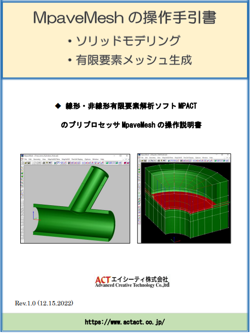
- CADを用いず解析対象とする幾何形状モデルの作成から有限要素メッシュ生成までを効率よく習得できるよう一連の操作手順を記述
- 多くの例題を通し、主要な有効機能を用いて分かり易く解説
- MpaveMeshのGUIの操作画面を具体的に図示し、説明
- MpaveMeshの操作コマンドの詳細内容を理解できるよう、「MpaveMeshリファレンスマニュアル」との関係記述を挿入
—
ーー
ーー
MpaveMeshのマニュアル(日本語版)Rev.3 リリースのお知らせ
「Rev.3(2022年11月)の特徴」 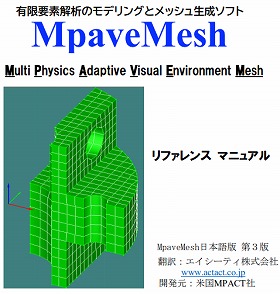
- これまでのドキュメントを見直し、誤字・脱字を訂正
- 各所に図表を入れ、分かり易い説明文を追加
- 理解を深めるため、具体的なモデリング及びメッシュ分割例を追加挿入
- 実用的に適用できるよう別マニュアル「MpaveMeshの使用手引書」(近日中にリリース予定)との関係づけ記述を随所に追加
—
ーー
ーー
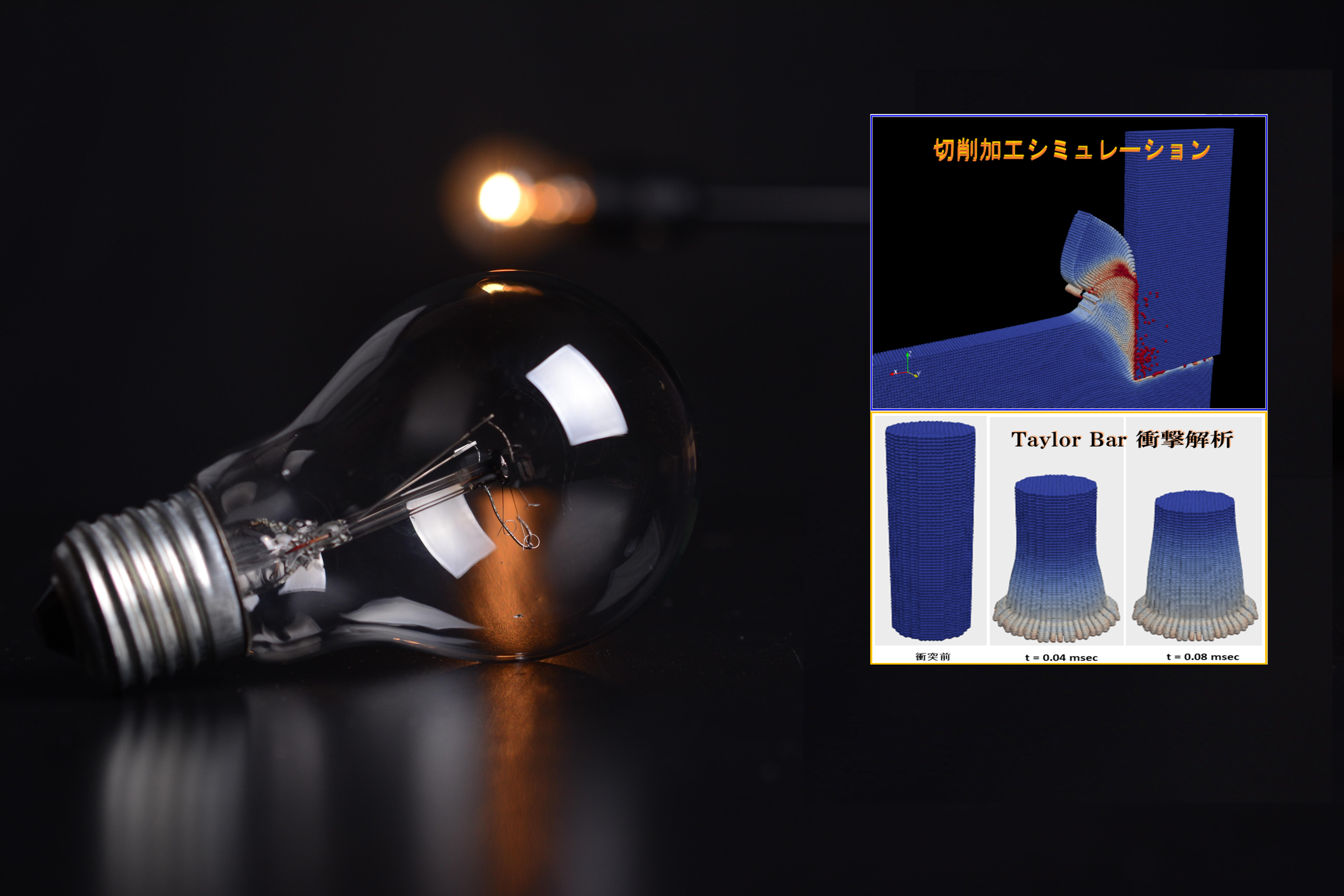
SPH粒子法による熱流体解析ソフトPHACT_Flow V.2.1の主な新機能
- 並列化処理機能搭載
- 解析手引書のアップデート(Rev.1.0 —> Rev.1.1)
- 「例題集」各種例題の追加と入力データ補足説明
- プリ・ポストプロセッサー(MpaveMesh, ParaView)の使用説明書の更新
- 発生したBug Fix、他
_________________________
_________________________
_________________________
[ セミナー・イベントのお知らせ ]ー
ーーーーーーーーーーーーーーーーーーーーー
ー
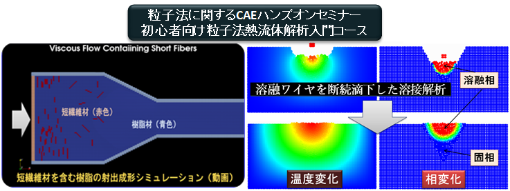
粒子法に関するCAEハンズオンセミナーのご案内
- コース名:初心者向け粒子法熱流体解析解析入門コース
- 日時:2024年6月17日(月)10:00 ~ 16:30
- 会場:としま産業振興プラザ 第2会議室(6階)
- 内容・申込み:コースの詳細内容・申込みについてはこちらから
- 主催:エイシーティ株式会社 共催:日本テクノフォート株式会社
—
ーー
————————————————————————————
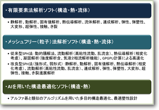
弊社では、広範囲の産業分野において解析シミュレーションソフトウェアの研究開発、販売、保守、およびコンサルティングサービスを実施しております。 その「特徴」は以下の通りです。(下図参照)
*製造、設計工程における複雑な材料挙動、機械特性を精度よくシミュレーションできるツールを持っています。
*ソースプログラムを持っていることより、お客様のニーズに合わせたカスタマイズができます。
*各産業分野で、豊富な解析実績があります。
*最新のAI(人工知能)技術を用いた最適形状解析が可能です
a:74297 t:15 y:17